
Start from the real plot
A site layout that starts from a rectangle on a blank page hides the constraints that matter — an irregular boundary, setbacks, access points. DCtoB starts by tracing the land boundary, so every building and yard is positioned on the actual site from the first step. It is the same starting point as a data center test-fit.
What goes on the site
Data halls
Sized from the rack count and density, and positioned first.
Power rooms
Packaged power-train containers — corrugated, plinthed and connected — with real service clearances.
Generator yard
Containerised gensets, roof silencers and bunded fuel, spaced for maintenance.
Chiller yard
Chillers, pumps and tanks laid out with the access they need for service.
Offices & support
Offices and support spaces modelled to scale beside the white space.
2D plans you can build from, and a 3D model you can explore
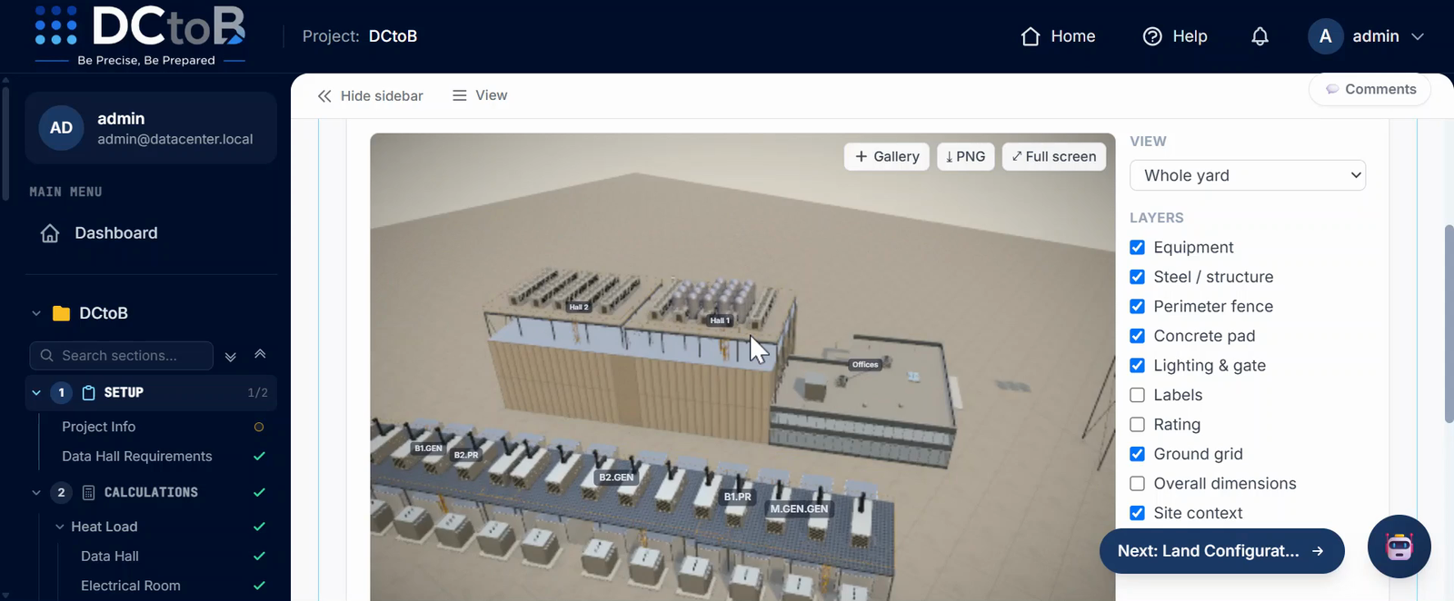
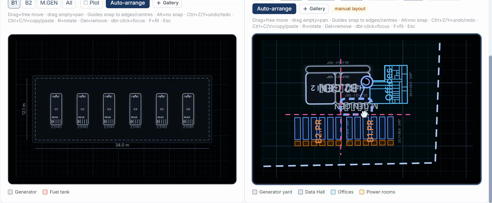
Every block has a dimensioned 2D plan — the power block with its service clearances, the generator yard with access roads and setbacks — and the whole site assembles into an interactive 3D model of the buildings and plant. Measure directly on the plans, and export the layouts and the 3D model as images for reports and presentations.
A layout that follows the design
Positions are part of the same model as the sizing, so the layout never shows equipment the design doesn't have. Add generators and the yard grows to hold them; change the number of halls and the site updates. The plant on the plan is the plant in the power and cooling sizing and the bill of quantities.
From layout to visuals
When the layout is settled, the finished model can be turned into photoreal, AI-rendered views of the whole facility — ready for a board presentation or a proposal.